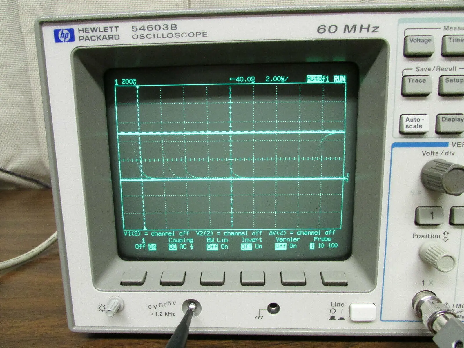
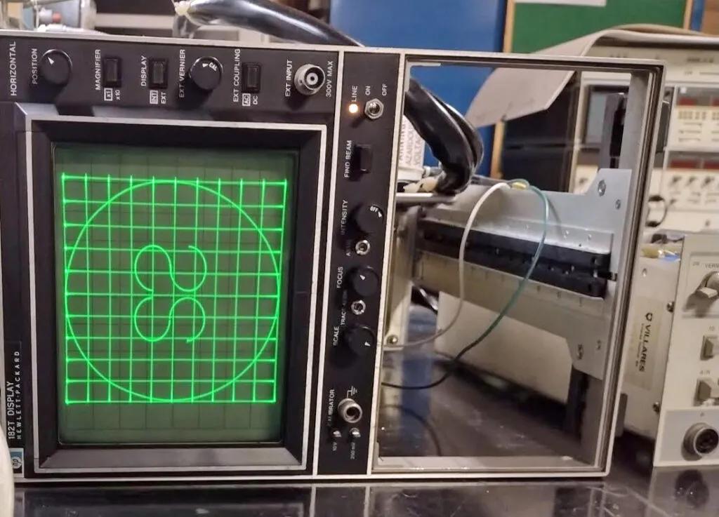
An oscilloscope is an essential tool for electronic engineers and technicians. It allows them to visualize and analyze electrical signals with precision. One of the key components of an oscilloscope is the internal shunt resistor, which plays a crucial role in the accurate measurement of current.
What is an Oscilloscope?
Before diving into the details of the internal shunt resistor, let's first understand what an oscilloscope is. An oscilloscope is a device used to measure and display voltage waveforms of electronic signals. It provides a visual representation of the signal's amplitude, frequency, and time characteristics. This information is vital for troubleshooting, analyzing, and designing electronic circuits.
The Purpose of an Internal Shunt Resistor
The internal shunt resistor is a critical component of an oscilloscope's current measurement system. It is designed to accurately measure the current flowing through a circuit under test. By connecting the circuit to the oscilloscope's input terminals and setting the appropriate scaling, the internal shunt resistor allows the user to obtain precise current measurements.
Sources of Error in Oscilloscope Measurements
When using an oscilloscope, it is essential to be aware of the potential sources of error that can affect the accuracy of measurements. Some common sources of error include:
- Noise: Electrical noise can interfere with the signal being measured, leading to inaccurate readings. It is crucial to minimize noise by using proper grounding techniques and shielding.
- Bandwidth Limitation: Oscilloscopes have a limited bandwidth, which means they can only accurately measure signals within a certain frequency range. If the signal being measured exceeds the oscilloscope's bandwidth, distortion may occur.
- Probe Loading: When connecting the oscilloscope probe to the circuit, it can introduce additional resistance, capacitance, and inductance, altering the characteristics of the circuit under test.
- Probe Compensation: Improper compensation of the oscilloscope probe can lead to measurement errors. It is crucial to adjust the probe compensation to match the oscilloscope's input impedance.
Components of an Oscilloscope
An oscilloscope consists of several key components that work together to provide accurate measurements. These components include:
 Analyzing hewlett-packard (hpe) stock price: trends, factors, and analyst targets
- Display: The display is where the waveform is visualized. It can be a cathode-ray tube (CRT) or a liquid crystal display (LCD).
- Input Amplifier: The input amplifier amplifies the weak electrical signals from the circuit under test to a level suitable for display.
- Triggering Circuit: The triggering circuit ensures that the oscilloscope captures and displays the waveform at the desired point in time. It helps stabilize the waveform and prevents it from drifting.
- Time Base Generator: The time base generator controls the horizontal sweep of the waveform on the display. It determines the time interval represented by each division on the screen.
- Vertical Amplifier: The vertical amplifier amplifies the voltage of the signal being measured to a level suitable for display.
- Internal Shunt Resistor: The internal shunt resistor is responsible for accurate current measurements.
Frequently Asked Questions
Q: How do I use an oscilloscope to obtain AC measurements?
A: To obtain AC measurements using an oscilloscope, connect the circuit under test to the oscilloscope's input terminals. Set the oscilloscope to AC coupling mode, adjust the vertical and horizontal scaling, and trigger the oscilloscope to display the desired waveform. The oscilloscope will then provide accurate measurements of the AC signal's amplitude, frequency, and other characteristics.
Q: What is the purpose of the triggering circuit in an oscilloscope?
A: The triggering circuit ensures that the oscilloscope captures and displays the waveform at a specific point in time. It helps stabilize the waveform on the display, preventing it from drifting or being distorted. The triggering circuit allows the user to set the trigger level and trigger mode, ensuring accurate and consistent waveform display.

The internal shunt resistor is a crucial component of an oscilloscope's current measurement system. It enables accurate current measurements, allowing electronic engineers and technicians to analyze and troubleshoot circuits with precision. Understanding the sources of error in oscilloscope measurements and the various components of an oscilloscope is essential for obtaining reliable and accurate results. By utilizing the internal shunt resistor and following proper measurement techniques, users can confidently rely on their oscilloscope for precise current measurements.
 Hpe careers: professional growth opportunities at hewlett packard enterprise
